3.3. VT AIR 310
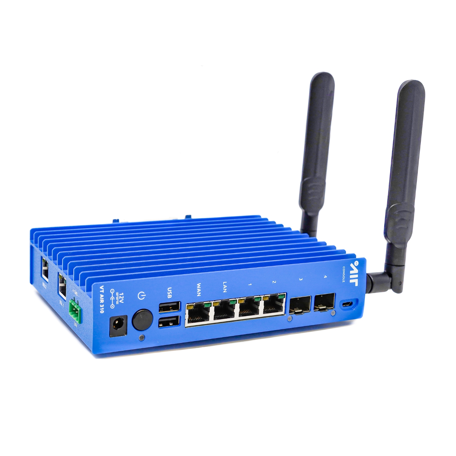
3.3.1. Overview
Summary of Features
CPU |
ARM64 |
CPU Cores |
4 Cores |
NIC |
2x 10GbE/1GbE SFP+/SFP Ports |
SSD |
16 GB eMMC |
RAM |
4 GB DDR4 |
Expansion |
2x DSL (VDSL/SHDSL) |
VDSL |
ADSL ITU-T G.992.1/3/5, VDSL2 ITU-T G.993.2, TR-048/067, TR-100, TR-114, |
SHDSL |
CO/CPE |
LTE |
LTE: B1 (2100), B2 (1900), B3 (1800), B4 (AWS), B7 (2600), B12 (700ac), |
Console-Port |
USB |
USB Ports |
2x USB 2.0 ports |
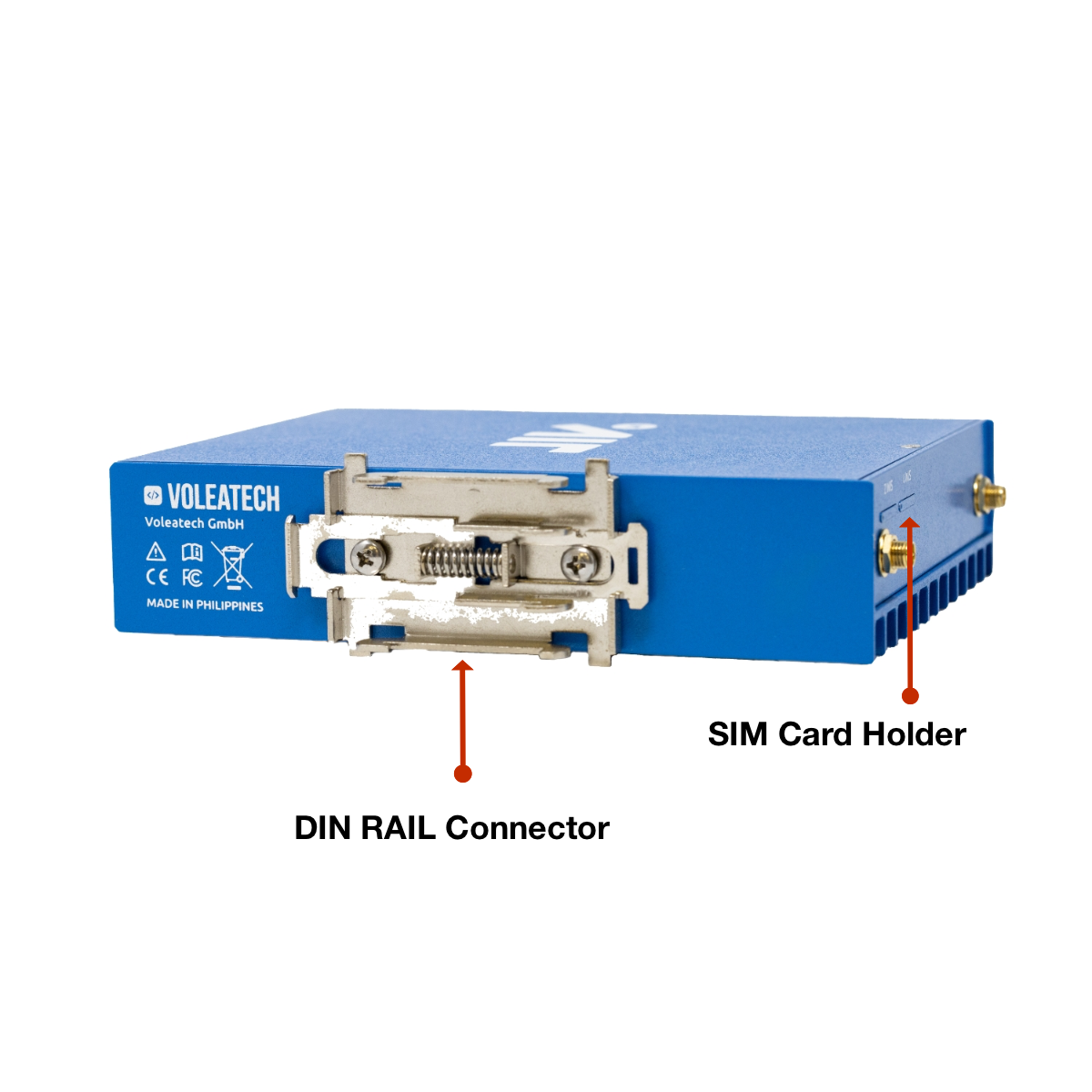
Mounting |
DIN rail mount |
Power |
12/24V via 1x 2.5mm DC plug |
Enviroment |
-20°C to 60°C Operating Temp |
Certificates |
CE, FCC, RoHS |
Software |
VT AIR Linux |
3.3.2. Industrial Usage
The product can be used in the industrial sector.
Electromagnetic Immunity: EN 55024, EN61000-4-2, EN61000- 4-3, EN61000-4-4, EN61000-4-5, EN61000-4-6, EN61000-4-8,
EN61000-4-11, EN 61000-6-2, EN 61326-1, IEC 61131-2 Electromagnetic Emission: FCC Class B, EN 55032, EN 61000-3-2,
EN 61000-3-3, EN 61000-6-4
Safety: EN 60950-1
3.3.3. External Connectors
Certified Cables
The following is a list of industry-standard cables, sorted by type, with the necessary compliance requirements that have been proven to work well with the VT AIR product family.
These examples are the cables which Voleatech uses for testing and should provide enough information to source products from your prefered cable vendor.
Ethernet cable: Monoprice 24AWG Cat6A 500MHz STP (max. 30m)
USB Cable: USB 2.0 Type A Male to Male Cable
USB Console Cable: USB 2.0 Type A Male to USB 2.0 Micro B Male Cable
USB Connector
The front USB connector supports USB 2.0 (Data rate of maximum 480 Mbit/s), connector type A. It can deliver up to 500 mA of power on each port.
LTE
If you bought the optional LTE configuration the Antenna can be mounted directly at the top of the unit. If you choose to use an Antenna cable, the device is certified for a cable length of up to 1m.
The main Antenna is in the back towards the DIN RAIL connector, the auxilirary Antenna is at the fronf of the device.
3.3.4. Packaging
The following items will be in the packaging of your VT AIR 310. Please make sure to check all items upon arrival of the device:
VT AIR 310 Device in the enclosure
Power adapter - 110V/220V US or EU plug
USB Console Cable: USB 2.0 Type A Male to USB 2.0 Micro B Male Cable
LTE Antennas (Only with LTE Kit)
RJ45 to 2 Pin connector (Only with SHDSL)
Phoenix Power Connector Adapter
Additionally, your device comes with different ports depending on your order:
1x or 2x SHDSL
1x or 2x VDSL
1x SHDSL, 1x VDSL
LTE Kit
mSATA
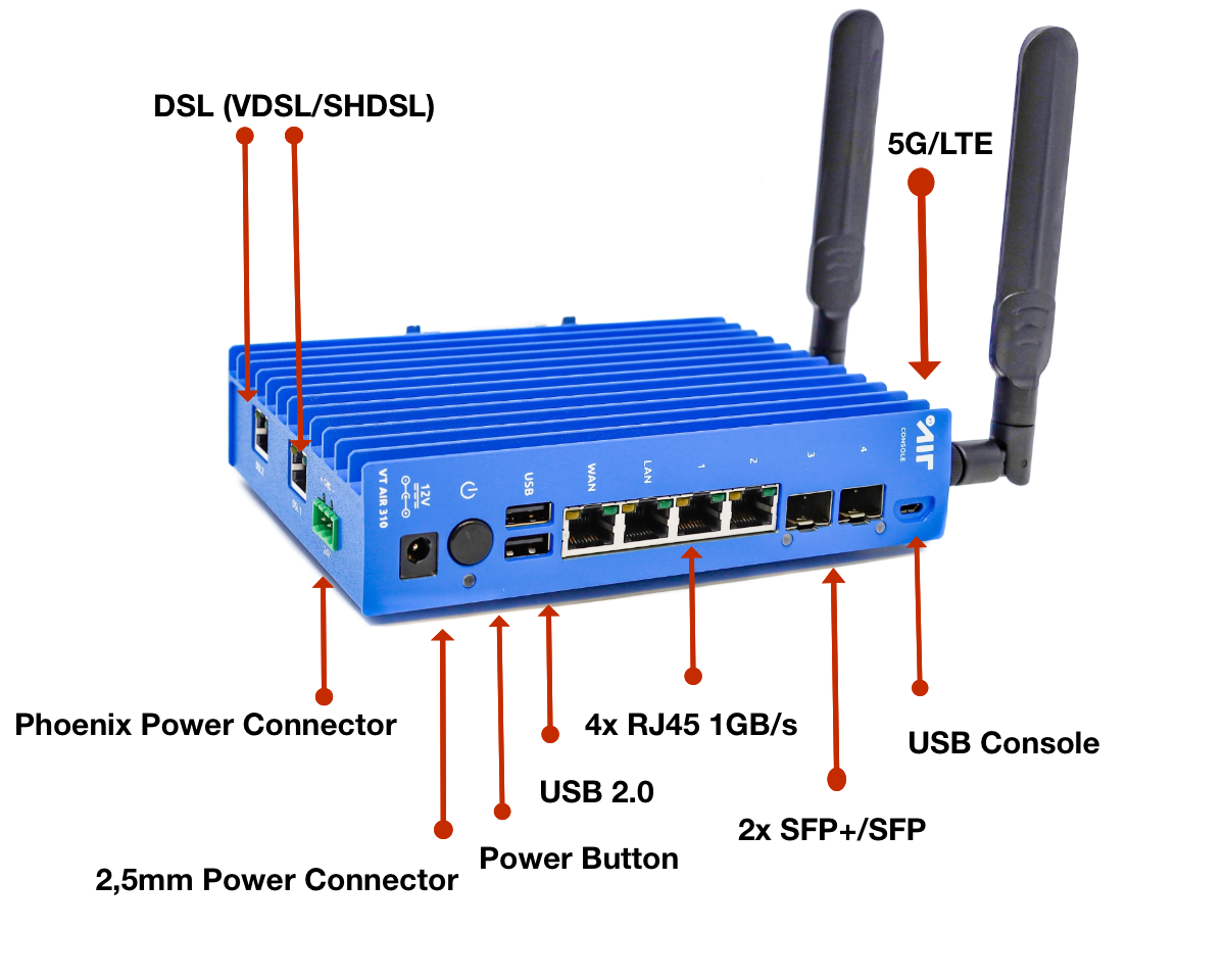
3.3.5. Ports
Front Conenctors
Network Ports |
|||||
|---|---|---|---|---|---|
eno0 (WAN) |
eno1 (LAN) |
eno2 |
eno3 |
eno4 (SFP) | eno5 (SFP) |
|
Label |
Software Name |
Features |
|---|---|---|
WAN |
eno0 |
RJ45 1000/100/10 Mbit/s |
LAN |
eno1 |
RJ45 1000/100/10 Mbit/s |
1 |
eno2 |
RJ45 1000/100/10 Mbit/s |
2 |
eno3 |
RJ45 1000/100/10 Mbit/s |
3 |
eno4 |
SFP+/SFP (10000/1000 Mbit/s) |
4 |
eno5 |
SFP+/SFP (10000/1000 Mbit/s) |
The RJ45 ports support Autonegotiation and Full Duplex or Half Duplex on all speeds.
The SFP/SFP+ Ports support the following Modules:
10Gb BaseT/SR/LR/LRM/ER/CR
1Gb BaseT/SR/LR/CR
There is no vendor lock for SFP modules. You can use any Module that conforms to the standard.
3.3.6. Power
The VT AIR 310 has 2 power connectors:
12/24VDC barrel connector
12/24VDC Phoenix/Euroblock connector
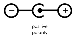
12/24VDC barrel connector
A suitable external power supply must be connected to the DC power socket, which has the dimensions 5.5mm x 2.5 mm
cylindrical barrel connector. The power supply must be 12 or 24VDC. Recommended values are: 12VDC/2A (no more than 5A).
Please note that the DC jack must have positive polarity in the center pin:
Warning
Please be aware that the maximum temperature for the barrel connector is 40°C.
12/24VDC Phoenix/Euroblock connector
A suitable external power supply must be connected to the DC Phoenix power connector. The power supply must be 12 or 24VDC.
Recommended values are: 24VDC/1A (no more than 3A).
Please note that the polarity is printed below the Phoenix power connector. Never connect the wrong polarity as the device
will break.
The middle pin can be used as grounding.
Warning
Only one power connector is allowed to be connected at any time!
3.3.7. USB Console
The appliance has a UART to USB bridge allowing convenient connection to the device console.
Such serial console connection is of USB-to-UART type. The connection speed should be set to 115200 bps.
All modern Operating Systems have a driver for the UART.
Windows
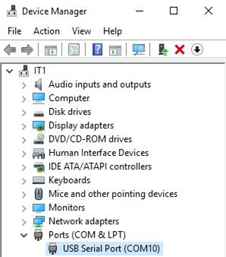
First you have to locate the COM Port number.
Open the Device Manager and expand the section for Ports (COM & LPT). Look for an entry with a title such as USB Serial Port.
A label is next to the name (COMX) where X is a number.
MacOSX
In OSX the device shows up at /dev/tty.usbserial-XXXXXX where X is a series of numbers and letters.
Linux
In Linux the device shows up at /dev/ttyUSBX where X is a number. You can also have a look at the output of dmesg to locate the newly connected device.
Terminal Program
A terminal program is required to open the connected serial port. We recommend:
OS |
Program |
|---|---|
Windows |
Putty |
MacOSX |
Screen, Serial |
Linux |
Screen |
3.3.7.1. First Connection to VT AIR Appliance
All VT AIR Appliances have a default LAN IP Address of 192.168.1.1 and the DHCP Server is active on LAN. Please make sure to locate the LAN interface of your appliance in the manual.
Connect your computer to the LAN Interface and receive an IP Address from the DHCP Server. It will be in the 192.168.1.X range.
After receiving the IP Address open a supported browser and navigate to https://192.168.1.1 A certificate warning will appear, since the VT AIR is using a self signed certificate. Please accept the certificate and continue to the page.
You will now be presented with the VT AIR login screen and you can use the default User and Password to login.
Note
User: admin Password: vtair
Please change the password after the first login.
3.3.8. VT AIR Reinstallation
Your VT AIR device comes pre-installed with its operating system. Should you ever need to reinstall the VT AIR operating system follow this guide.
3.3.8.1. Download the Installer File
You can download the installer file from your Portal (see Downloads for details). Make sure to download the file for your specific model/architecture.
3.3.8.2. USB Flash Drive Preparation
Once you downloaded the file make sure your USB flash drive is at least 2 GB in size. Also backup all your files from the USB flash drive since it will be formatted in the process and all files on it will be deleted.
3.3.8.3. Download the Software
Download and install the software balenaEtcher from www.balena.io/etcher. It is available for Windows, macOS and Linux. Select the software for your specific operating system.
3.3.8.4. Use the Software
Insert your USB flash drive into the computer. Start the balenaEtcher software.
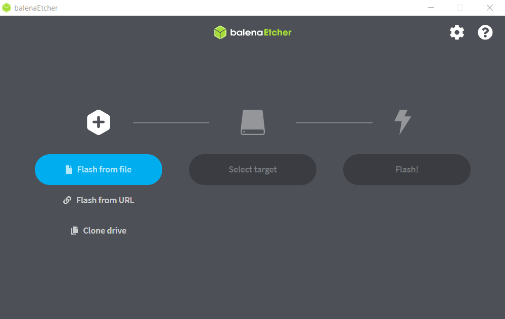
Press Flash from file
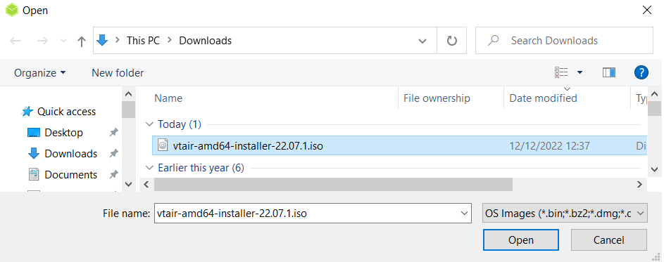
Select the downloaded installer file with the ending .iso
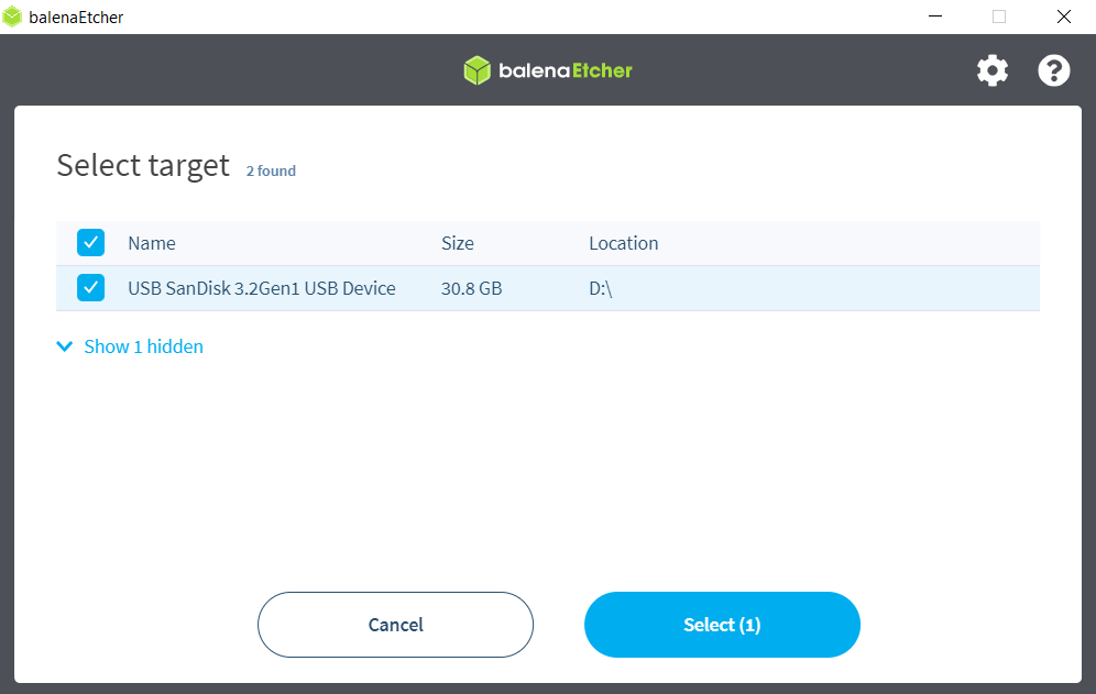
Select your USB flash drive as target
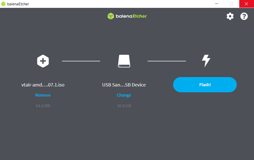
Press Flash! to complete and wait until the process is finished. Close the software and remove the USB flash drive from your computer.
3.3.8.5. Install the Software
Insert the USB flash drive with the new VT AIR operating system in your VT AIR’s USB port.
3.3.8.6. Serial Console Installation
Connect the USB cable to the Console USB port of your VT AIR device and your computer. On your computer connect to your VT AIR’s Console (see Console Access).
Type “reboot” to reboot the system. In the boot process you’ll see a timer that you can interrupt by pressing any key. This gives you a shell from where you can reinstall your OS.
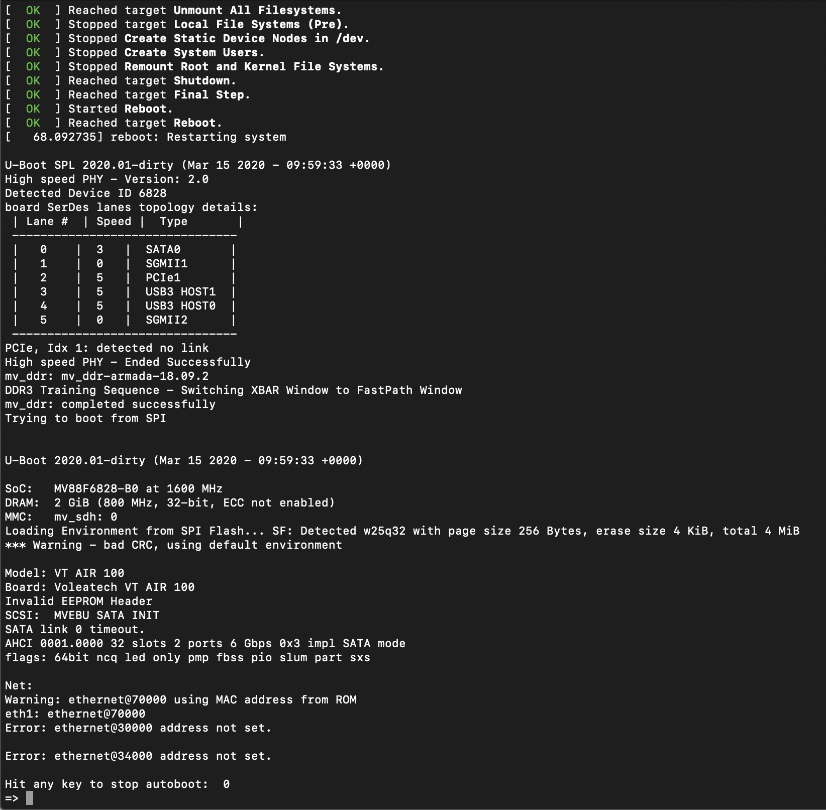
Type “run install” to run the OS installer from your USB stick. The installer runs without any user inputs.
3.3.9. LEDs
The VT AIR 310 has multiple LEDs. They are indicating for example power on, connection and port activity. Ethernet port related LEDs are embedded in the RJ45 connectors, while the power indicator LED is located below the serial port.
The RJ45 NIC LEDs are configured the following way:
LED Activity |
Explanation |
|---|---|
Off |
No connection |
Green Light Only |
100Mbit/s Speed |
Green and Yellow Light |
1000Mbit/s Speed |
SFP LED
The SFP LED is software controlled and will be green if the configured and active SFP interface is up and has a physical connection to the other end. The SFP interface has to be configured and enabled for the LED to work otherwise it will stay off.
SHDSL LEDs
If your order includes a SHDSL card you will also have 2 LEDs on each SHDSL RJ45 connector. The left LED is for power on and will be on when the SHDSL port is ready to do a connection. The right LED has three different modes:
LED Activity |
Explanation |
|---|---|
Slow Blinking |
Searching for remote modem |
Fast Blinking |
Connection parameters are being negotiated |
Steady Light |
Connection established |
VDSL LEDS
If your order includes a VDSL card you will also have 2 LEDs on each RJ45 connector. The left LED is for power on and will be on when the VDSL port is ready to do a connection. The right LED has three different modes:
LED Activity |
Explanation |
|---|---|
Slow Blinking |
Searching for remote modem |
Fast Blinking |
Connection parameters are being negotiated |
Steady Light |
Connection established |
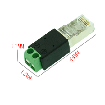
3.3.10. SHDSL
The optional SHDSL modems only use 2 PINs of the RJ45 connector, PIN4 and PIN5. It does not matter in which order two SHDSL modems are connected to each other the PINs can be swapped.
We add a RJ45 to 2 PIN connector for each SHDSL modem.
3.3.11. Operational Data
Operational Voltage
Item |
Voltage |
Current |
Ambient Temperature |
|---|---|---|---|
Front barrel connector |
12 or 24 VDC |
2.0 A |
Max. 40°C |
Phoenix/Euroblock connector |
12 or 24 VDC |
2.0 A |
Max. 60°C |
Enviromental Data
The environmental temperature data are based upon the component with the lowest available temperature. Please make sure to check which addons you ordered and make sure not to exceed the allowed ambient temperature.
Warning
Failure to comply with the allowed ambient temperature may void the warranty of your device.
Ambient Temperature |
Minimum |
Maximum |
|---|---|---|
Base Device/LTE |
-20°C |
60°C |
VDSL |
-20°C |
50°C |
SHDSL |
-20°C |
50°C |
Humidity (non-condensing) |
10 % |
90 % |
Leave a minimum of 2cm of space on both sides of the device when installed on a DIN Rail.
For ambient temperatures above 30°C, leave 5cm space on both sides of the device for air cooling to work properly.
Grounding
The device can be grounded through the DIN RAIL connector. The case dissipates high currents across the DIN RAIL connector.
The middle pin of the Phoenix plug can also be used as grounding. Please note that this can dissipate only a low current, in comparison to the DIN rail.
3.3.12. Warranty Terms and Conditions
Voleatech GmbH guarantees its hardware products against defects in workmanship and material for a period of one (1) year from
the date of shipment. Under warranty, the customer’s sole remedy and Voleatech’s sole liability shall be, at Voleatech’s sole
discretion, to either repair or replace the defective hardware product at no charge.
This warranty is void if the hardware product has been altered or damaged by an accident, misuse or abuse or is not operated
according to this manual.
For additional information on warranty and related topics like RMA, please visit www.voleatech.de.
Disclaimer of Warranty THIS WARRANTY IS MADE IN LIEU OF ANY OTHER WARRANTY, WHETHER EXPRESSED, OR IMPLIED, OF MERCHANTABILITY, FITNESS FOR A SPECIFIC PURPOSE, NONINFRINGEMENT OR THEIR EQUIVALENTS UNDER THE LAWS OF ANY JURISDICTION, EXCEPT THE WARRANTY EXPRESSLY STATED HEREIN. THE REMEDIES SET FORTH HEREIN SHALL BE THE SOLE AND EXCLUSIVE REMEDIES OF ANY CUSTOMER OR PURCHASER WITH RESPECT TO ANY DEFECTIVE PRODUCT.
Limitation on Liability UNDER NO CIRCUMSTANCES SHALL VOLEATECH GmbH BE LIABLE FOR ANY LOSS, DAMAGE OR EXPENSES INCURRED OR WITH RESPECT TO ANY DEFECTIVE PRODUCT. IN NO EVENT SHALL Voleatech GmbH BE LIABLE FOR ANY INCIDENTAL OR CONSEQUENTIAL DAMAGES THAT CUSTOMER MAY SUFFER DIRECTLY OR INDIRECTLY FROM THE USAGE OF ANY PRODUCT. BY ORDERING THE VT AIR 310, THE CUSTOMER APPROVES THAT THE VT AIR 310, HARDWARE AND SOFTWARE, WAS THOROUGHLY TESTED AND HAS MET THE CUSTOMER’S REQUIREMETS AND SPECIFICATIONS.
3.3.13. LEGAL NOTICE
Voleatech GmbH (hereinafter “Voleatech”) products and services are sold subject to Voleatech terms and conditions of sale,
delivery and payment supplied at the time of purchase order acknowledgement. Voleatech warrants the performance of its products
according to actual specifications at the date of shipment. Voleatech reserves the right to make changes to its products and
specifications or to discontinue any product, product line or service without prior notice.
Customers should make sure to obtain in each case the latest version of relevant product information from Voleatech and to
always verify for themselves that their requirements are met and reference is up to date. Product testing and all additional
quality control techniques are utilized to the extent that Voleatech deems necessary to support their warranty and warranty
terms. Therefore detailed testing of all parameters in any product is not necessarily performed in full unless required by law
or regulation.
In order to minimize risks that may be associated with customer products, applications or services, the customer must use
adequate design and operating safeguards to minimize any possible hazards. Voleatech is not liable for any applications
assistance or customer product design and thus it is the customer’s sole responsibility to make the selection and usage of
Voleatech products. Voleatech is not liable for any such selection or usage thereinafter and neither is liable for the usage of
any circuitry or components other than completely and entirely embodied in a Voleatech product. Furthermore Voleatech is not
liable for its products commercial fit for any market segment envisioned by the customer.
Voleatech products are not intended for use in life support systems, appliances, nuclear systems or systems where malfunction
can reasonably be expected to result in personal injury, death or severe property or environmental damage. Any use of
Voleatech’s products by the customer for such purposes is completely at the customer’s own risk.
Voleatech does not grant any license -expressed or implied- on any patent right, copyright, mask work right, type or model
protection or any other intellectual property right (IPR) of Voleatech covering or relating to any product combination, hardware,
machine, software or process in which its products or services might be or are used. Any provision or publication of any third
party’s products or services does not constitute Voleatech’s approval, license, warranty or endorsement thereof. Any third party
trademarks contained in this document belong to the respective third party owner.
Reproduction of content and information from Voleatech documents and manuals is permissible only if reproduction is without
alteration and is accompanied by all associated copyright, proprietary and other notices (including this notice) and related
conditions. Voleatech is not liable for any un-authorized alteration of such content and information or for any reliance
related to alterations thereon. Any representations made, warranties given, and/or liabilities accepted by any person which
differ from those contained in this manual or in Voleatech’s standard terms and conditions of sale, delivery and payment are
made, given and/or accepted at customer’s own risk. Voleatech is not liable for any such representations, warranties or
liabilities or for any reliance thereon by any person.
3.3.14. Regulatory
This chapter provides regulatory and compliance information about Voleatech’s VT AIR 310 -related information.
Product name: VT AIR 310
Safety Notice
Before you begin using this product, please read the following safety information. Attention to these warnings will help prevent
personal injuries and damage to the products.
It is your responsibility to use the product in an appropriate manner. This product is designed for use solely indoor
environments or, if expressly permitted, also in the field and must not be used in any way that may cause personal injury or
property damage.
You are responsible if the product is used for any intention other than its designated purpose or in disregard of Voleatech‘s
instructions. Voleatech shall assume no responsibility for such use of the product.
The product is used for its designated purpose if it is used in accordance with its product documentation and within its
performance limits.
Safety Information and Notices
Never turn on or connect to power any equipment when there is evidence of mechanical damage, fire, exposure to water, or structural damage.
When not in use, avoid placing or storing the product in the following places or under the following conditions:
Ambient temperature above 40°C
Exposed to direct sunlight
Humid or exposed to dust
Warning
This product does not contain any user replicable or serviceable parts. Do not take apart or attempt to service the product yourself.
Never remove the cover or any part of the housing of the product.
The internal battery is not user replicable.
In the event of an equipment malfunction, all repairs must be performed either by Voleatech GmbH or by an authorized agent. It is the customer responsibility to report the need for service to Voleatech GmbH or to one of the authorized agents. For service information, contact Voleatech GmbH customer support.
Be careful not subject the product to strong impact.
If the product was subjected to a strong impact and/or falling over check carefully for any damage to the product. If such damage is observed the use of the product must be stopped immediately.
Operation
The product may be operated only under the operating conditions as specified by Voleatech GmbH.
When the product is used for an extended period of time, and/or at high ambient temperature and/or exposed to direct sunlight
it is normal for the product body to feel warm.
Avoid overheating the product.
The product’s ventilation should not be obstructed or blocked. If proper ventilation is not provided it can result in battery
overheating or explosion of the battery resulting fire, burns or other injuries.
Stop using the product immediately if it emits smoke or a strange smell, or otherwise behaves abnormally.
Following are the required operating position and conditions:
Do not place the product on unstable surfaces
Do not place the product on elevated surface and secure it from falling from high places on passerby
Do not place the product on heat-generating surface or near heat emitting devices or direct flame. Verify that there is sufficient clearance between the product and any other device exhaust warm air
The product operating ambient range can be found at Environmental Data. Voleatech GmbH recommends that an ambient temperature of 0 to 40 °C (32 to 104 °F) and relative humidity of 30-50% is maintained during normal operation as this will result in better performance and longer life of the equipment. Temperature must not exceed the maximum temperature specified in Environmental Data.
Do not expose the product to moisture or dust.
The product is not liquid-proof; therefore, the equipment must be protected against penetration by liquids. If the necessary precautions are not taken, the user may suffer electric shock or the product itself may be damaged, which can also lead to personal injury.
Never use the product under conditions in which condensation has formed or can form in or on the product, e.g. if the product has been moved from a cold to a warm environment. Penetration by water increases the risk of electric shock.
AC/DC Adapter or Power Supply - Electrical Safety
The following information on electrical safety must be observed, failing to follow these instruction may result in electric shock, fire and/or serious personal injury or death.
Use only the adapter or power supply supplied with the product or adapter or power supply with the following specifications:
Output voltage of 12V or 24V and current of at least 2A and not more than 3A.
Prior to powering the product and plugging the adapter or power supply to the mains supply, always ensure that the nominal voltage setting on the adapter or power supply matches the nominal voltage of the AC supply network.
If extension cords or connector strips are implemented, they must be checked on a regular basis to ensure that they are safe to use.
Never use the adapter or power supply if the power cable is damaged. Check the power cable on a regular basis to ensure that it is in proper operating condition. By taking appropriate safety measures and carefully laying the power cable, you can ensure that the cable will not be damaged and that no one can be hurt by, for example, tripping over the cable or suffering an electric shock.
Do not insert the plug into sockets that are dusty or dirty. Insert the plug firmly and all the way into the socket. Otherwise, sparks that result in fire and/or injuries may occur.
Do not overload any sockets, extension cords or connector strips; doing so can cause fire or electric shocks.
Do not insert or remove the plug with wet hands.
Never remove the cover or any part of the housing of the adapter or power supply, doing so will expose circuits and components and can lead to electric shock, injuries, fire or damage to the product.
The adapter or power supply operating ambient temperature range is of 0 to 40°C / 32 to 104 °F (storage temp range: -20 to 60 °C / -04 to 140 °F) maximum operating altitude is 2000 m ASL.
Use suitable overvoltage protection to ensure that no overvoltage (such as that caused by a bolt of lightning) can reach the product. Otherwise, the person operating the product will be exposed to the danger of an electric shock.
The product is not liquid-proof; therefore, the equipment must be protected against penetration by liquids. If the necessary precautions are not taken, the user may suffer electric shock or the product itself may be damaged, which can also lead to personal injury.
Never use the product under conditions in which condensation has formed or can form in or on the product, e.g. if the product has been moved from a cold to a warm environment. Penetration by water increases the risk of electric shock.
Prior to cleaning the product, disconnect it completely from the power supply. Use a soft, non-linting cloth to clean the product. Never use chemical cleaning agents such as alcohol, acetone or diluents for cellulose lacquers.
Electronic Emission Notices (EMC)
Federal Communications Commission Declaration of Conformity
The following information refers to VT AIR 310.
This equipment has been tested and found to comply with the limits for a Class B digital device, pursuant to part 15 of the
FCC Rules. These limits are designed to provide reasonable protection against harmful interference when the equipment is
operated in a commercial environment. This equipment generates, uses, and can radiate radio frequency energy and, if not
installed and used in accordance with the instruction manual, may cause harmful interference to radio communications.
Operation of this equipment in a residential area is likely to cause harmful interference in which case the user will be
required to correct the interference at their own expense.
Responsible Party:
Voleatech GmbH
Gratwohlstr. 5
72762 Reutlingen
Germany
European Union - Compliance to the Electromagnetic Compatibility
(EMC) Directive or Radio Equipment Directive
This product is in conformity with the protection requirements of EU Council Directive 2014/30/EU (from 20 April, 2016) on the approximation of the laws of the Member States relating to electromagnetic compatibility.
Voleatech GmbH is not responsible for any radio or television interference caused by using other than specified or recommended cables and connectors or by unauthorized changes or modifications to this equipment.
Unauthorized changes or modifications could void the user’s authority to operate the equipment.
WEEE and recycling statements
The WEEE marking on Voleatech GmbH products applies to countries with WEEE and e-waste regulations (for example, the European WEEE Directive). Appliances are labeled in accordance with local regulations concerning waste electrical and electronic equipment (WEEE).
These regulations determine the framework for the return and recycling of used appliances as applicable within each geography. This label is applied to various products to indicate that the product is not to be thrown away, but rather put in the established collection systems for reclaiming these end of life products.
Users of electrical and electronic equipment (EEE) with the WEEE marking must not dispose of end of life EEE as unsorted municipal waste, but use the collection framework available to them for the return, recycle and recovery of WEEE and to minimize any potential effects of EEE on the environment and human health due to the presence of hazardous substances. Voleatech GmbH electrical and electronic equipment (EEE) may contain parts and components, which at end-of-life might qualify as hazardous waste.
EEE and waste electrical and electronic equipment (WEEE) can be delivered free of charge to the place of sale or any distributor that sells electrical and electronic equipment of the same nature and function as the used EEE or WEEE.
Restriction of Hazardous Substances (RoHS) European Union RoHS
This product, with included parts (cables, cords, and so on) meets the requirements of Directive 2011/65/EU and directive 2015/863/EU on the restriction of the use of certain hazardous substances in electrical and electronic equipment (“RoHS recast” or “RoHS 2”).
EU Radio Directive Equipment (RED)
Declaration of Conformity (DoC)
Voleatech declares that the radio equipment for the VT AIR 310 is in compliance with Radio Equipment Directive 2014/53/EU.
LTE Modem
Warning
A safety distance of at least 20 cm must be kept between the product antenna and the operator or and other persons.
3.3.15. Contact Information and Resources
Voleatech GmbH
Gratwohlstr. 5
72762 Reutlingen
Germany
www.voleatech.de
info@voleatech.de
+49 7121 539 550